Bass Drum Maths
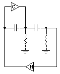
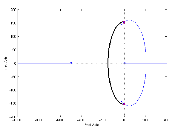
 If you're up to reading this material then you'll recognise this circuit as the base of the TR808 style analog bass drum. It is a single RC "T" filter with a feedback amplifier (H), this topology is often used as a simple oscillator. The bass drum circuit also utilises a feed forward compensator (C) to control the decay, but exactly how does it work?
The filter is easily tunable by varying the resistive branch of the network, and for the sake of this simulation a resistive load has been placed on the output of the filter to help match real world conditions more closely.
 Splitting the system down into a "classical" control system is done with the block diagram on the right. This topology breaks the circuit down into the equations below. Sensible values have been substituted for the resistor and capacitor values to result in rather rounded equations, but they don't fall far from practice.
|
| ||||
| H = 100 |
|

